Access Begins With Building Geometry
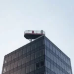
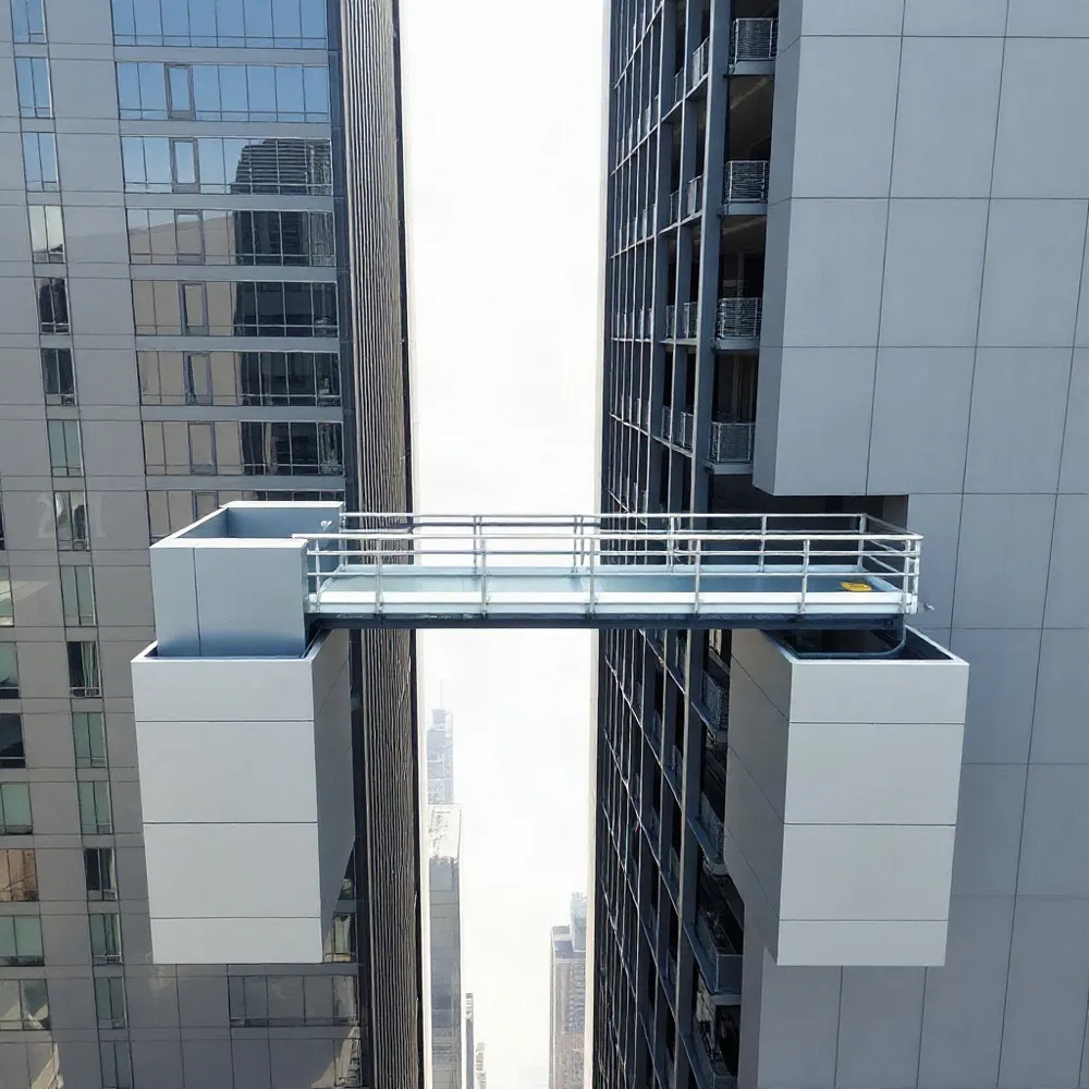
Setbacks, curved or sloping elevations, deep projections and limited roof space can prevent conventional access equipment from reaching every part of a façade. For high-rise buildings, these constraints affect routine cleaning, inspection, repairs and glazing work, so access must be considered alongside the building’s geometry.
Permanent access is an engineering requirement, not equipment to add after the design is complete. Early coordination helps align façade coverage with roof layout, structural capacity, operating clearances and the intended appearance of the building. The U.S. General Services Administration’s accessible facility design guidance offers a useful user-centred principle, though its regulatory requirements apply to U.S. federal facilities, not UAE projects.
There is no single system for every project. Sea Star Engineering designs permanent access equipment, including purpose-made cradles, around building geometry and maintenance needs. UAE project teams can assess whether a building maintenance unit, roof-mounted cradle or another configuration provides suitable reach while accounting for structural and architectural constraints.
Define the Access Requirement
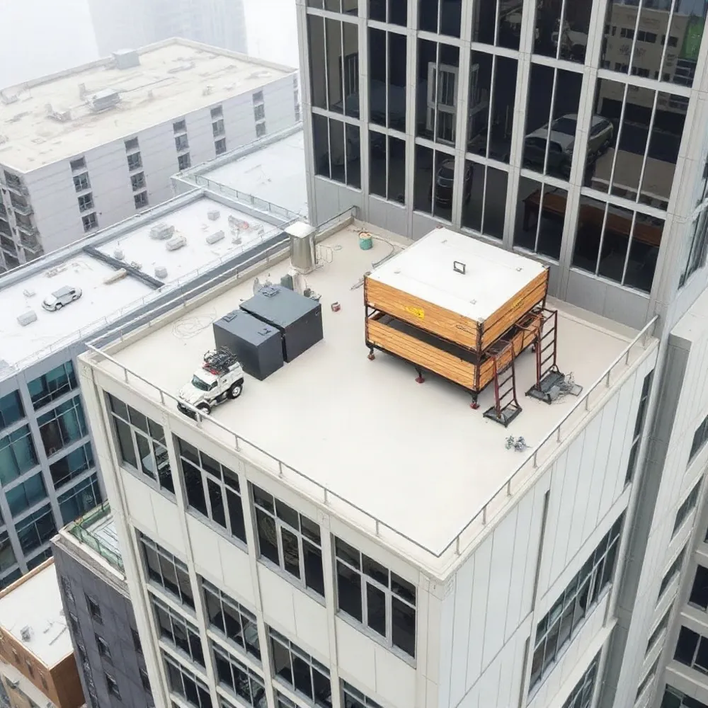
System selection should start with the work the building must support, not a preferred machine type. Building height, façade geometry, roof capacity and layout, available operating space, and maintenance frequency all affect whether a project needs a mechanized unit, suspended cradle, davit arrangement, or a combination.
List the anticipated tasks and their equipment needs: routine cleaning, façade inspection, glazing replacement, cladding and sealant repairs, and maintenance of external lighting or signage. Glass replacement may require space to position panels, suitable lifting capacity, and a clear route for materials. These requirements should be defined early so the access system can serve both routine work and less frequent repairs.
Map the Complete Operating Journey
The design should account for each step, from reaching the roof and the equipment to moving across the roof, deploying the system, reaching work areas, handling tools and materials, and returning to a safe area. Check routes against roof plant, edges, level changes, storage positions, and equipment clearances. A system that reaches the façade but cannot be accessed or operated safely from the roof is not a complete solution.
Bring architects, structural and façade engineers, owners, facility managers, and access-equipment specialists into coordination while the design can still respond to their requirements. Review structural loads, façade coverage, roof space, power, parking positions, and maintenance routes together. Early coordination can reveal conflicts that would otherwise constrain a retrofit; Sea Star Engineering’s project-specific design approach supports this assessment for permanent access systems.
Match Equipment to the Façade
Once maintenance tasks and access routes are established, the equipment can be matched to the façade’s geometry. A permanent Building Maintenance Unit (BMU) may combine roof tracks or a traversing trolley, a mast or jib, hoists, wire ropes and a suspended platform. The configuration depends on reach, roof capacity, available operating space and the work the unit must perform.
Telescopic or articulated jibs can extend over projections or reach recessed areas. Tracks and monorails provide defined routes around a building, while pantograph platforms can keep a working platform aligned with sloped surfaces. Where a mechanized unit is unsuitable, rope access or davit arrangements may offer an alternative, provided anchor locations, rope paths and safe working positions are engineered for the site.
Restricted roof space or a desire to limit visible equipment may call for a compact, trackless or otherwise tailored arrangement. These options are not interchangeable: the roof structure, façade coverage, equipment movement, parking position and maintenance method all need assessment.
The platform and lifting arrangement should reflect the actual task. Glass replacement may require a suitable hoist and working space for handling panels, while cradle dimensions, reach and carrying capacity must be specified for the planned loads rather than assumed. Sea Star Engineering’s custom access equipment can be tailored to these operational requirements. For projects with limited roof area, a compact system may help address space constraints, but its reach and coverage still require project-specific engineering.
Integrate Structure and Safety
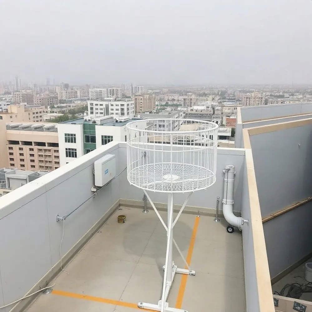
A façade access system must work with the building’s structure, roof build-up and operating layout. Engineers should assess equipment weight and operational forces, confirm support capacity and coordinate tracks, anchors and other connections with the load path. Roof penetrations also need detailing for waterproofing, insulation and drainage.
Resolve equipment routes, operating zones and parking positions alongside rooftop plant, screens and maintenance clearances. Allow for power and control connections, safe access to the equipment, and clear routes for operators and materials.
Specify safety provisions to suit the system and risk assessment. Depending on the configuration, these may include secure platforms, harness anchor points, redundant wire ropes, fail-safe brakes, emergency controls and wind monitoring. The design should also address emergency recovery, safe egress and inspection access, so checks and maintenance can be carried out without creating new access risks.
Coordination among structural, architectural, façade and access-equipment teams helps resolve conflicts before installation. Sea Star Engineering designs and installs permanent building access equipment as part of a turnkey service, supporting coordination between the equipment and the building interfaces it depends on. Applicable regulations and equipment standards must be confirmed for the project’s jurisdiction; standards cited in other countries should not be assumed to govern UAE projects.
Learn From Project-Specific Solutions
Project examples show how access arrangements can respond to several constraints at once. At Shanghai Tower, a double-layer transparent curtain wall left little room for Building Maintenance Units (BMUs), while sloping elevations and unusual roof angles complicated façade coverage. The project used seven BMUs with davit arms, alongside a purpose-developed three-dimensional climbing BMU.
Manntech’s project account says the climbing unit could change its climbing angle and direction of travel at the same point on its route, and describes this capability as a first for that level of geometric complexity. This is a project-specific solution, not a standard specification.
The Burj Khalifa offers a UAE example of distributed access. Its distinctive form and limited roof or terrace space made a conventional roof-based arrangement unsuitable. The project account describes 18 bespoke machines positioned across multiple levels and tiers, rather than one roof-mounted system.
Neither project should be treated as a template. Engineers must resolve reach, equipment routes, parking or storage positions and complete façade coverage against each building’s structure and operating needs.
Plan for Operation and Service Life
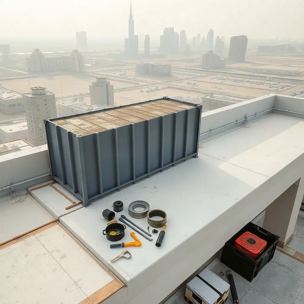
Whole-life planning should weigh more than initial equipment cost. Account for installation, expected use, inspections, servicing, replacement parts, future façade repairs and changes in maintenance needs over the building’s life.
Operational planning should also define routine checks of cables, wear and emergency systems, operator training, service records, and periodic inspections or recertification where required.
Features such as ergonomic platforms, cable management, wind alerts and task-specific accessories can support safe, practical work, but should be selected to suit the project rather than assumed as standard. A well-integrated permanent system can reduce reliance on temporary access methods and limit maintenance disruption. Its performance still depends on project-specific engineering and ongoing maintenance.
Engineer Access Into the Design
Non-standard architecture calls for access planned around façade geometry, maintenance tasks, structural capacity and safe operating routes. Coordinate permanent equipment early, verify full coverage and operating constraints, then define inspection and service arrangements to support reliable access throughout the building’s life.